

T0 -- the time from start to shearing of the flying shearing machine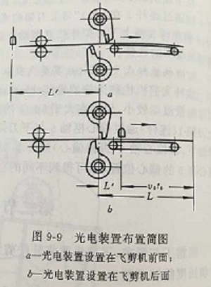
When adjusting the length of the ruler, the method of moving the position of the photoelectric device (that is, changing the L 'value) is not usually adopted, but the time t0 is changed through the time relay or programmable controller. In order to make the ends of the sheared parts not prevent the photoelectric device from acting again in the next shearing, a certain gap must be made between the sheared parts and the remaining parts. This requirement is usually achieved by increasing the speed of the shear roller.
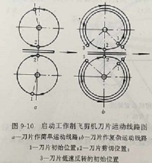
Obviously, only when the start and braking of the flying shears can be guaranteed within the interval between two shears can the flying shears be cut normally. However, the heavy and high speed flying shear often has no time to complete the starting and braking requirements within a circle, that is, the blade speed cannot be accelerated to the rolling part's motion speed at the shear position and the blade cannot stop at the initial position after shear. At this point, more complex motion lines (figure 9-10b) are needed to replace the usually simple motion lines (figure 9-10a). FIG. 9-10a shows that the rolling speed of the blade reaches when the blade is accelerated from the initial position 1 to the rotation position 2 after the fly shear is started. After shearing, the kinetic energy of the fly shear mechanism makes the blade stop at the initial position 1. FIG. 9-10b shows that when the fly shear machine starts, the blade accelerates from the initial position 1 to the shear position 2, and the motion speed of the rolled piece is reached for parallel shear. After shearing, the blade stops in segments 2-3 and reverses from position 3 to initial position 1, ready for shearing again


